

About PLCLearn More
Programmable logic controllers or PLCs are rugged computers used to monitor and control automated mechanisms. They are most often used in a factory production environment. PLCs can also manage and monitor many other systems, such as roller coasters, food production, lighting arrays, and many others. Udemy offers a variety of courses that can teach you the finer points of PLC.
Sort by:
Sorting
The newest
Most visited
Course time
Subtitle
Filtering
Courses


Udemy

Dilipkumar Sharma
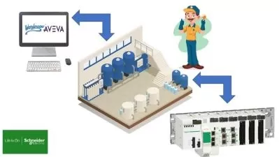
Wonderware Intouch Scada Alarm logging using Schneider PLC 2:05:58
12/26/2024


Udemy

Engineer Rodrigo
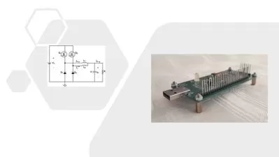
VFD Drives, Frequency Inverters, Complete PLC Course Drives 16:44:01
05/20/2024
Udemy
Engineer Rodrigo
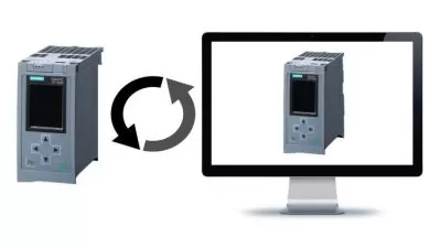
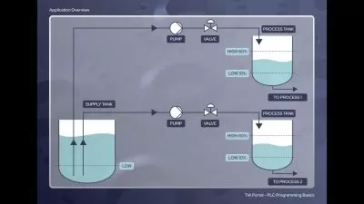
SIEMENS TIA PORTAL PLC Course Basic & Intermediate Pt1 PLC 15:34:31
05/19/2024


Frequently asked questions about PLC
A programmable logic controller or PLC is a solid-state computer designed for the manufacturing industry. PLCs monitor the information they get back from input devices and then make decisions based on that state. Those input devices that the PLC devices monitor are attached to industrial machines used in manufacturing processes. The PLC can adjust the way these machines operate based on this feedback. PLCs started replacing relay logic systems in the 1960s, as they are more reliable and easier to troubleshoot than the older relay-based system. Because of the harsh environments where PLCs must operate, their design is rugged enough to withstand extreme temperatures and shock. They are also programmable and modular, so technicians can tweak a manufacturing process with code and apply the same change elsewhere by just copying its code.
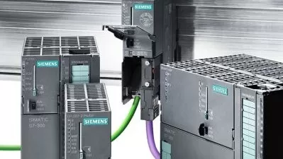
The core of a PLC is the CPU or central processing unit. This consists of more than just the main microprocessor. It also contains the memory chip for the device and any other integrated circuits required for its operation. You will usually find it close to the PLC's power supply. The power supply converts the current coming into the device to the voltage levels required for the CPU and other components. Other main parts of a PLC include the input module and the output module. The input module encodes the signals coming from sensors that monitor equipment into data the CPU can use. Once the data is available, the output module translates the signals coming from the CPUs to the output devices. A PLC will also have a bus system to handle digital signal flow inside the device and a rack or rail that the PLC mounts on.
SCADA stands for Supervisory Control and Data Acquisition. It is a system of software and hardware that an industrial enterprise can use to control manufacturing processes both on-site and from remote locations. With SCADA, you can monitor and process real-time data coming from industrial processes and directly interact with these remote devices with human-machine interface software. In fact, you can observe and record every step of the manufacturing process. The resulting data is useful for modifying processes for better efficiency in the future. A SCADA system begins with PLCs that connect to factory equipment and sensors. The PLCs collect data that routes to central computers running SCADA software. The SCADA software processes this data and distributes commands back to the PLCs.
You can use five common programming languages in PLCs. The most commonly used is ladder logic, or ladder diagram (LD), a graphical PLC programming language. It is structured to be like relay logic, replacing the switches and coils used by physical relays with PLC memory locations and input/output modules. Sequential function charts (SFC) is another language compatible with PLC. You'll notice that it resembles a flowchart that has multiple branches. The third PLC language is function block diagram (FBD). This one is a graphical language like LD and uses blocks to represent functions with lines connecting them. Structured text (ST), the fourth language, is a text-based language like Basic, Pascal, or C. ST is powerful and can do more low-level processing than the graphical options. Last on the list is instruction list (IL), which is also textual and is even more low level resembling the Assembly Language.
Programmable logic controllers, or PLCs, operate in a loop that involves four steps. Details of each step will be unique depending on the system. This process starts with an input scan. The PLC scans all inputs to detect the state of all the devices connected to the system. After that comes the program scan. During this step, any custom logic written for the PLC will execute. The purpose of this logic is to make decisions based on the input data from the devices and then complete step three in the process. Step three is the output scan. At this point, the result of the custom logic makes adjustments to the output devices connected to the PLC. The fourth and final step of the PLC loop is the housekeeping step. This step includes garbage collection, internal diagnostics, and other processes, so the next loop starts cleanly.
The four main components of a programmable logic controller include the CPU, the power supply, the input module, and the output module. CPUs are the processing unit of the PLC and consist of a microprocessor, memory chip, and other integrated circuits to control logic and monitoring. The power supply converts the power coming into the PLC to the required voltage level for the device. You can think of input modules as the interface between the sensors that monitor equipment and the CPU, while output modules are the bridge between the CPU and the output devices. Additional parts might include the rack it mounts to and the device for programming it, which can be a standard PC with specialized software installed or a custom programming unit. It all depends on how you define parts of a PLC.